Notifications

6 minutes, 56 seconds
-40 Views 0 Comments 0 Likes 0 Reviews
Pneumatic control valves are vital components in many industrial systems, enabling precise control of fluid and gas flow by converting compressed air into mechanical motion. These China Control Valves are widely used in automated processes that demand efficient and reliable flow regulation. Understanding their construction, common faults, and troubleshooting techniques is key to maintaining performance and minimizing downtime.
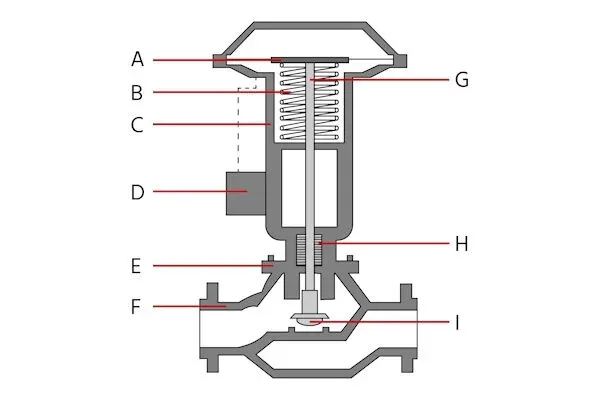
A pneumatic control valve comprises several critical parts, each designed to support accurate and reliable valve operation:
The actuator converts air pressure into mechanical force to move the valve stem and adjust flow. It comes in two main types:
Diaphragm Actuators – Ideal for low-pressure applications; they provide fast response using a flexible diaphragm.
Piston Actuators – Better suited for high-pressure systems due to their robust design.
Actuators are further classified into:
Single-Acting: Air moves the valve in one direction, and a spring returns it when pressure is removed.
Double-Acting: Air pressure moves the valve in both directions, offering better control and faster response.
In single-acting systems, the spring ensures the valve returns to a default safe position if air pressure fails—crucial for safety-critical operations.
The yoke links the actuator to the valve body and maintains alignment, especially in high-pressure or high-vibration systems. A well-built yoke prevents misalignment and wear.
The positioner ensures the valve moves to and holds the desired position. It receives control signals and adjusts the actuator accordingly. Types include:
Pneumatic: Operate using air signals.
Electro-Pneumatic: Translate electric signals to air signals for precise control.
Digital: Offer advanced diagnostics and real-time feedback via microprocessors.
The bonnet houses and protects the valve stem and internal components. It also maintains a pressure-tight seal and allows for internal access during maintenance.
This is the main housing that holds the internal flow control components. Valve body types vary depending on the application:
Globe Valves – Best for precise throttling.
Ball Valves – Fast open/close, minimal pressure drop.
Butterfly Valves – Ideal for large flow and low pressure.
Gate Valves – Typically used for on/off control.
The valve stem connects the actuator to the plug or disc. It must resist stress, torque, and vibration while maintaining a tight seal.
These components prevent leakage of air and fluid. Over time, seals degrade and require inspection and replacement to maintain efficiency.
This pair determines the flow rate. The plug moves into or away from the seat to control flow. The quality and materials used in the seat and plug affect sealing performance and longevity.
Even with proper design, pneumatic valves may encounter operational issues. Common faults include:
Caused by worn seals, cracked hoses, or loose fittings. Air leaks reduce actuator efficiency and can lead to inconsistent valve operation.
Often caused by debris, corrosion, or rust. This restricts valve movement and may cause partial or complete flow blockage.
Failures result from pressure loss, internal damage, or excessive wear. A faulty actuator can leave the valve stuck in one position.
Incorrect calibration, signal interference, or electrical faults can cause the valve to operate out of sync with control inputs.
Old or damaged seals can compromise pressure integrity, causing air or fluid leaks and reducing performance.
A methodical approach is essential for identifying and resolving issues. Here’s a step-by-step guide:
Start by reviewing service history to spot recurring issues or patterns.
Look for visible signs of damage, corrosion, misalignment, or wear on the actuator, yoke, and connections.
Use a gauge to verify correct air pressure. Inspect supply lines for leaks, blockages, or pressure drops.
Ensure smooth movement when air is applied. Listen for hissing sounds indicating leaks or diaphragm failure.
Follow manufacturer instructions to ensure accurate positioning. Check signal quality and rule out interference.
Confirm the control system sends accurate, consistent signals. Look for wiring issues or signal mismatches.
Operate the valve manually to feel for smooth travel and listen for grinding or knocking noises.
If necessary, disassemble the valve to clean debris and examine wear on the stem, plug, seat, and seals.
Check for clogs, corrosion, or restrictions that may interfere with valve performance.
Pneumatic control valves are essential for precision flow control in automated industrial systems. Understanding their construction and recognizing common issues—like air leaks, actuator failure, or seal degradation—can help you maintain performance and avoid unplanned downtime. With regular inspections, proper calibration, and a structured troubleshooting process, these valves can deliver long-term reliability and safety across a wide range of applications.Know more about Google SEO Directory

